Close Ad

How To Lower a ’88-’98 Chevy Using Belltech!

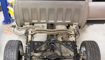
Lowering a ’88-’98 Chevy Using a 4/6 Belltech Kit

When considering a lowering kit for your 1988-1998 C1500 or (OBS GM Truck), you’ll find there are quite a few options out there. Most companies offer parts individually, so you can get creative with parts combinations in order to get your desired results. In our case, we wanted to try and get this job done with performance and ultimate ride quality in mind. Being that Belltech Suspension was a huge part of the sport truck movement back in the ’90s, the company knows a thing or two about OBS GM trucks.  With that said, naturally they were our first call when we decided to tackle the suspension on our 1990 C1500.  

We decided to utilize the 3-inch drop spring and paired those with the 2-inch drop spindle up front. To achieve our desired drop out back, we went with a flip kit. The flip kit is also adjustable drop because it comes with new rear shackle mounts that when paired with the flip kit will yield either a 7 inch or 8 inch.  We topped everything off with Street Performance Shocks/Shock extenders and front and rear sway bar kit.

Belltech lowering kits include all the parts and pieces you need to achieve not only the look you want, but the alignment, and performance and safety you need. These complete lowering kits are your all-in-one-box solution, providing you with all the necessary parts to lower your truck. Made up of a variety of combinations as well as all the installation and alignment pieces necessary to achieve the listed lowering, choosing your kit has never been simpler. And the install is even easier! Let’s get started.

"<yoastmark

 Factory brake caliper on an 1988-1998 C1500
After removing the wheel, we started disassembling the factory front suspension. Our first step here was to remove the factory brake caliper, which can be accomplished by loosening the two large Allen head bolts that hold it to the spindle.
removing the hub/brake rotor assembly
When removing the hub/brake rotor assembly, you must first remove the factory dust cap, which can be accomplished by using a flathead screwdriver to gently pry the cap away from the rotor. If it has never been removed this may require you to tap the screwdriver gently with a hammer to get it between the rotor surface and the cap.
Belltech lowering kit install
We then removed the spindle castle nut and slid the hub/brake rotor assembly off the spindle, then we were able to remove the dust shield by removing the three bolts holding it to the spindle.
With the outer tie rod nut removed, we used a hammer to free the tie rod from the spindle. A common mistake that people make when doing a job like this at home is hitting the tie rod. A couple good whacks with a heavy hammer on the spindle itself will free the tie rod. Never hit the tie rod itself, it will damage the tie rod and it won’t help free it anyway.
At this point you’ll need to put a floor jack under the lower control arm applying some pressure, but not enough to lift the truck off of the jack stands. We always position the jack so that the handle is facing the front of the truck and the jack can be operated from this position.
Removing shocks on an 1988-1998 Chevy
Our next step was to remove the shock. This is done by removing one nut at the top of the shock stud and the two lower shock bolts that go up through the lower control arm, and then you can remove the shock through the opening in the lower control arm.
Upper and lower control arm assemblies for a Belltech lowering kit
We will be replacing our upper and lower control arm assemblies during this installation, so we went ahead and removed all 4 control arm bolts, the sway bar end links from the lower control arms and removed the upper and lower control arms.

 Belltech springs
We then re-installed our control arms and positioned the new Belltech spring into the spring pocket (it helps to have someone hold the spring in place for you) then position the jack back under the lower control arm with light pressure on the arm.  Now you can place the spindle on the lower ball joint stud, lower the upper control arm down to position the ball joint stud back through the new spindle and then secure the spindle by installing the ball joint nuts and new cotter pins (we do not recommend re-using old cotter pins). We then installed our new Belltech street performance shock through the lower control arm re-using our original bolts.
Next up is the hub/brake rotor assembly.  Going back together we opted for all new bearings, seals and rotors.  You can re-install your old assembly, however either way you decide to go, we recommend having your rotors turned, new seals and re-packing your bearings at a minimum.

We applied some self-etching primer and rattle can black to our new rotors to prevent flash rust. After this was done we moved on to packing our new bearings and installing the new seals on the hub/rotor assembly.  (If you do not have a seal install kit, you can find a socket that has the same overall diameter as your seal).

Belltech lowering kit install

Belltech tie rods
Our next step was to assemble our new inner and outer tie rods with new our new adjusters and attach them to the new drop spindle using the new nut and cotter pin.

Now it’s time to ditch the old front sway bar in favor of our new one from belltech, but first we must remove our factory sway bar.  This was a breeze since our sway bar end links were already disconnected.
We began preparing our new sway bar by applying the provided bushing grease to the contact areas of the new bushings, and installing the bushings with brackets. We went ahead and assembled the end links and installed them on the sway bar.
We then moved the sway bar underneath the truck and into its mounting location. It’s best to have someone to help with this step by holding it up into position.  If you don’t have an extra set of hands you can use your floor jack to hold it in position.  Once this is done we attached the sway bar end links to the lower control arms.  You’ll want to leave them loose for now and then come back and tighten them.  At this point you can line the sway bar bushing brackets up with the threaded holes in the frame and install the 4 bolts you removed earlier.
To finish off the front suspension we went back over everything and did a good nut and bolt check ensuring to torque everything to factory specs. Also this is a great time to hit all of those grease points on the front end.
Our first task on the rear suspension was to remove the bed.  This kit can be installed without doing this, however we recommend removal of the bed.  We removed the 8 bed bolts, fuel filler flange, ground strap near the fuel filler neck, ground for the taillight harness, and unplugged the taillight harness near the rear of the frame.  We were lucky enough to have an overhead crane in the shop to assist in the removal of the bed, however this can be accomplished by bribing a few friends with free pizza and something cold to drink.  We took this opportunity to do a quick pressure wash of the chassis before we got started.  This isn’t just for cosmetic reasons.  Removing all of the old gunk can help speed up the process when removing old parts and hardware.

We then removed the receiver hitch, factory shocks, the spare tire, and the old rusty tailpipes that had to go due to clearance issues.
We could then turn our attention to the axle and getting it ready to be flipped.  With the truck on jack stands (supporting the chassis) and the rear end supported by our floor jack we then removed the factory u bolts and leaf spring plates. Now you can lower the rear end away from the leaf spring packs, but not so far that it puts tension on the rear brake line.
Now it was necessary to remove the bolts that secure the brake line and wiring harness to the inside of the frame rail.  There are two bolts securing the brake line transitioning fitting to the chassis and two bolts securing the rigid brake line and electrical wiring to the chassis.  These parts are secured in nylon clips that must be clear of the chassis while we do our cutting and installing of the c-notch.

We then used the supplied template and some chalk to mark our cut lines for the c notch.  In the upper corners of our cut marks we used a ½” drill bit to drill a hole in each corner.  Now on to our favorite part, the cutting! cut the chassis along the lines we scribed in the previous step.  This can be done with an angle grinder with a cut off wheel, plasma cutter or reciprocating saw.

With our chassis cut we were now able to line up our c notch utilizing the locating holes and clamp it in place utilizing a c clamp.  Make sure the C-section top flange is in contact with the top of the vehicle chassis.  Now utilizing the ½” holes in the C-section as a guides, we drilled through the 8 holes on the side and the 2 on the bottom.  We then installed the kit supplied hardware.
Now on to getting the axle back in place!  At this time we hung the front of the leaf spring by re-installing the factory bolt and nut through the bracket and leaf spring eyelet.  Utilizing our floor jack we lifted our rear end high enough to allow us to swing the rear of the leaf spring pack back up into the factory leaf spring bracket.  At this point we re-installed the factory bolts into the shackle and left everything hand tight.  It is important not to tighten the leaf spring bolts until the weight of the vehicle is on the springs.
Our next step was to position the new Belltech axle saddle brackets, and secure everything with the new grade 8 u bolts, locking nuts and leaf spring plates.  Make sure the “ears” on the axle tube saddle locate under the edges of the rear axle tube spring pad.
With all of the lowering components installed on the rear of the chassis, we could move on to getting that beefy rear sway bar installed.  We began by assembling the end links and loosely installing them on the sway bar and using the kit supplied bushing grease to lubricate the contact areas of the bushings.
The last step before re-installing the bed was to go back over all of our hardware and torque to factory and manufacturer specifications……..and of course admire our new belltech suspension. We then re-installed the bed and re-connected our grounds and taillight harnesses. It is very important that you bring the truck straight to an alignment shop and have it properly aligned for safety and to prevent premature wear on your expensive tires.
Here’s a better photo of the completed truck, after alignment and ready to be driven. We are super happy with the overall ride quality of the truck. The results are a very noticeable drop, without giving up any ride quality, and without having to trim anything out due to tire rubbing.

RIDETECH AIR SUSPENSION | PROJECT ARTEMIS PART 2

Project Artemis Ridetech Air Suspension Install.

 A couple of issues back, we introduced you to not only our latest project truck known as Artemis but also a new tech team helping out on this year’s OBS build. SaltWorks Fab in Myakka City, Florida, is known for building some amazing hotrods and trophy-winning showpieces for customers. With way more expendable income than we do, so having the crew take time out of their busy schedule to help us document Artemis’ RideTech suspension swap is an honor we are proud to boast about. So, if you missed the February ’21 issue where we documented the front suspension install, we suggest you head over to www.engagedmediamags.com to buy a copy while you can. In this issue, we tackle the rear of our 1998 GMC Sierra 1500 SLE. A C-notch install and a lot of sweet-looking, well-engineered suspension parts.

We said it in the last issue, but it stands repeating. This is a completely bolt-on air-ride suspension for ’88-’98 Chevy/GMC 2WD trucks.

No cutting the bed floor and no removing the fender liners. Just a C-notch and a quick shave of the bed brace. All the permanent modifications that needed to be made. They’re nothing that would stop us from putting it back to stock one day if we wanted to. Which is what we were looking for in an air suspension system. This Ridetech system also has electronic ride height sensors that set your ride height to whatever PSI you want. This way, even if you have a leak. The system will correct it at the push of a button until you can pull off and make a repair.

The final piece to the new suspension puzzle is picking a wheel and tire package. For project Artemis, we wanted a setup that would allow us to have a super low stance without cutting anything and a decent ride on 40-series tires. If you have any experience with air suspension, county roads and 35-series tires, you will more than likely understand our desires for this driver. The wheels are staggered fit, 20-inch aluminum wheels from US Mags with a width of 8 inches up front, and 9.5 inches in the back. Having a wider wheel in the back not only looks cool, but it also stretches the 40-series tire just a bit to give up some extra clearance out back when cruising low and slow. Now let’s check out the steps to installing the rear of this extremely well-engineered air suspension system for GMT400 trucks.

C-notch install
In this issue, we tackle the rear of our 1998 GMC Sierra 1500 SLE with a C-notch install and a lot of sweet-looking, well-engineered suspension parts. If you missed the February ’21 issue where we documented the front suspension install, we suggest you head over to www.engagedmediamags.com to buy a copy while you can. Until then, step one, of course, is removing the bed.
Rear frame rail ready for c-notch
With this Ridetech suspension system, the only major modification you need to make to your ’88-’98 Chevy or GMC truck. Is to add a C-notch to the rear frame rail. This is a simple yet tedious process that must be done in order to get as low as possible. By allowing additional clearance for the axle to travel up, while bringing the body of the truck down.

Drilling frame for c-notch

Grinding out frame for c-notch
Lots of guys have their own technique for cutting a notch, and generally they all work great, but the way the team at SaltWorks performed the task made it look basic beyond belief. Trace the pattern, drill some relief holes in the corners, grind down the gunk so you don’t ruin your blade, and simply use a grinder to remove the piece. (Editor’s note: Be sure to properly support both sides of the frame to avoid any drooping or sagging.)

Installing ridetech c-notch

With the Ridetech provided C-notch in place, they drilled all the bolts and bolted it onto place. You may be surprised by just how much additional strength these give to the chassis.
Ridetech lower bag mount bracket
Next, the lower bag mount brackets are installed on the rear axle using a set of U-bolts provided in the kit.
With the bracket in place, the front of the parallel link bars can be bolted into the factory leaf spring location.

Now the rear of the link bar can be bolted to the lower bag bracket mounting point.
Ridetech upper wishbone bracket
Next to the upper wishbone bracket is installed. This piece bolts into the C-notch on both sides and eventually ties to the differential.

This differential bracket easily bolts to the rearend and the upper crossmember. It’s a very, very well-engineered design and fits absolutely perfectly.

Ridetech shockwave
The Ridetech shockwave airbag is next to be installed. It simply bolts into place behind the axle and allows for plenty of wheel clearance.

The final pieces to the mechanical parts puzzle are the ride height sensors. These digital do-gooders keep the truck height in check by maintaining pressure to your pre-desired setting.
Here you can see the complete rear suspension installed and ready to be covered by the bed—but before that we need to coat that frame!

kbs undercoating

KBS Coatings is our go to source for frame and fuel tank coatings. This spray-on rubberized undercoating not only prevents rust and corrosion, but it also helps with sound deadening which is great for a 20-plus-year-old truck!
Before the bed can go on, we snipped off the back of the exhaust pipe so it doesn’t clank on the axle while driving. We will be replacing this in the next issue with an all new Flowmaster exhaust from Holley Performance.

Next up, the bed can be bolted back into place and the fun part begins—ruining electrical wires and airline! But that’s after they mount the air tank.

Organizing and planning are a big part of any major modification, and this one is no different. Deciding which way to route the black airline and which wires need to go where is not a task for the tired. So, if you’ve been working long hours with no sleep, hold off on this step until after your nap.

This is a completely bolt-on air-ride suspension for ’88-’98 Chevy/GMC 2WD trucks. No cutting the bed floor and no removing the fender liners.

When attaching the hose to the frame, be sure to give it some slack in case you need to trim the ends a few times. The last thing you want is to have to replace an entire airline for a few missing inches. Once it’s all complete, the battery power can be connected and tested. Time to turn the key!
You can’t hear it in the picture, but this baby is buzzing with energy from the dual compressors filling up the air tank.
That first time setting any suspension project on the ground is exciting. Nicole even broke away from her digital duties to show her love of the low.

Us Mags

Our choice for wheels is this ultra-bright chrome Bullet design from US Mags. These are staggered fit, 20-inch aluminum wheels. With a width of 8 inches up front and 9.5 inches in the back. If you have any experience with air suspension, county roads and 35-series tires. You will more than likely understand our desires for a 40-series tire. Having a wider wheel in the back not only looks cool. But it also stretches the 40-series tire just a bit. To give up some extra clearance out back.
Man, she looks good! Those wheels are the perfect fit, and the stance is impressive. Since we didn’t have to cut anything major away from the factory truck.

Before we can take it for a test ride, we need to coat the bed with a real bedliner. This will prevent it from rusting near the drill holes and will look amazing next to the new wrap.
Speaking of wrap, here’s a little teaser!